Port definitions in CENOS
An essential element of your RF simulation is the port and it is important to figure out how to define it properly. For this reason, we need to understand what kind of options we have and make modifications to our model, if necessary.
For most applications, you won’t need to modify your geometry to feed your model, as defining a port in CENOS RF has been made incredibly straightforward and can be done with your existing geometry.
Currently there are three types of port definitions in CENOS:
- Discrete port
- Coaxial port
- Waveguide port
Discrete port
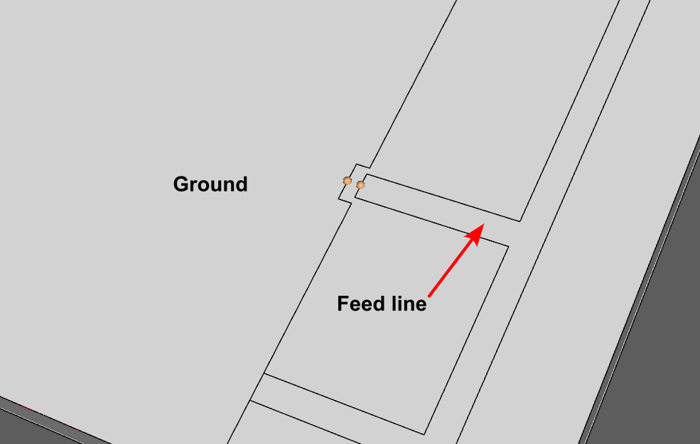
The discrete port in CENOS is the simplest way to define the feed of your model. Essentially, all you have to do is to select two terminals - one on each conductive surface where you connect the feed in real life. The placement of each of the terminals is dependent on the type of model you are simulating.
For example, if you are simulating a simple microstrip antenna, such as an IFA, you would place one terminal on the edge of the feed line of the microstrip and the other on the closest edge of the ground plane.
If you are simulating a symmetrical design, such as a dipole antenna, you would have to place a point on each pole, leaving a gap in between the poles.
Coaxial port
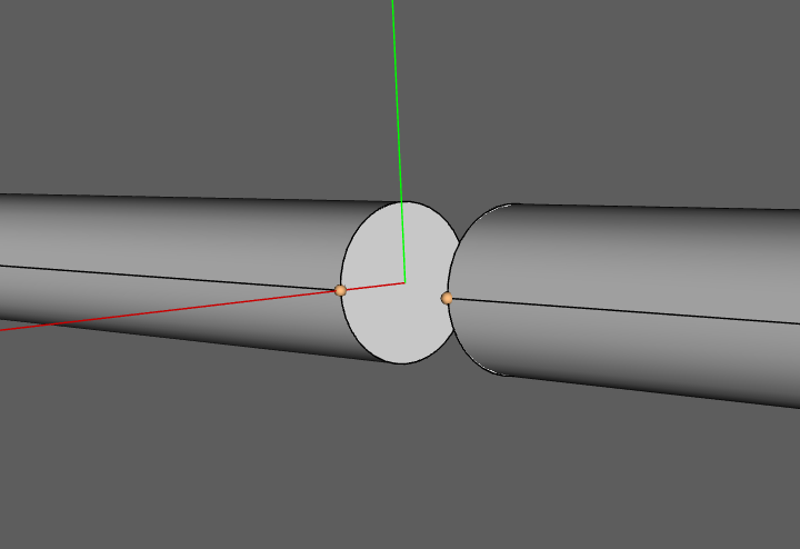
Coaxial ports are ports where the connection surface is made by a coaxial connector or cable. If your model already contains the geometry for the cable or connector, all you have to do is to select the surface of the dielectric to define such a port.
tip
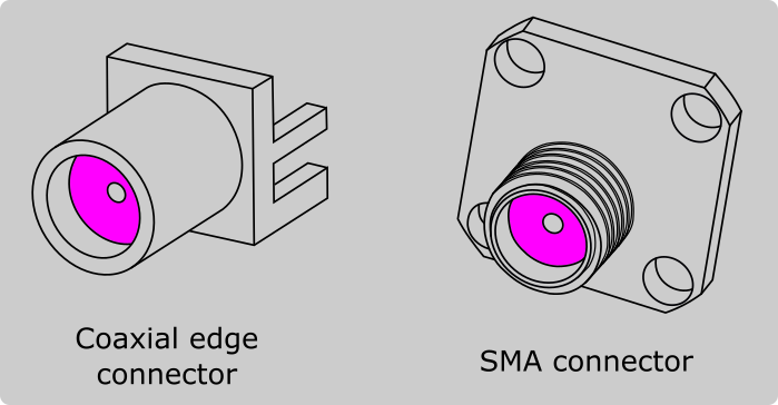
You can create a coaxial connector yourself or use one from the Component Library in FreeCAD.
important
Ensure that both the internal conductor of the connector and the dielectric are aligned and terminated in the same plane on the side where you will define the coaxial port. This alignment is crucial for maintaining signal integrity and achieving optimal performance of the coaxial port.
Here is a quick video tutorial on setting up a coaxial port and it's necessary roles:
Waveguide port
When you are working with waveguides, it is necessary to use the Waveguide port for this purpose. The port will be defined as a face in the model, and for this it is necessary to create the dielectric that is inside the waveguide, once you have it, simply select the necessary face.
Port geometry simplification
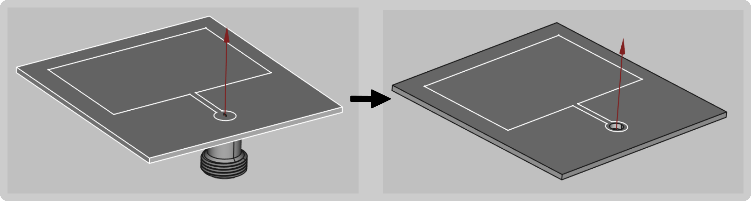
Quite frequently it makes sense to simplify your geometry in order to make the mesh smaller, and in turn reduce the overall calculation time. If your model contains a coaxial connector, you can choose to remove it from your design and use a discrete port instead.
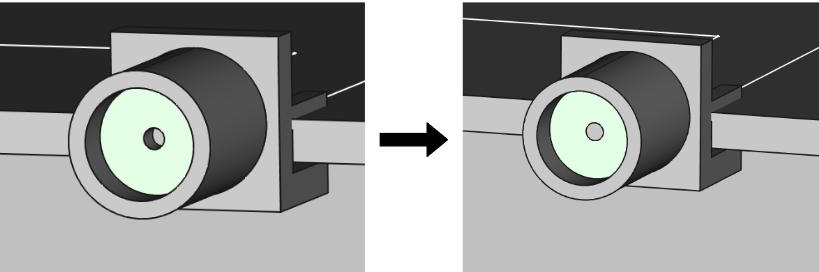
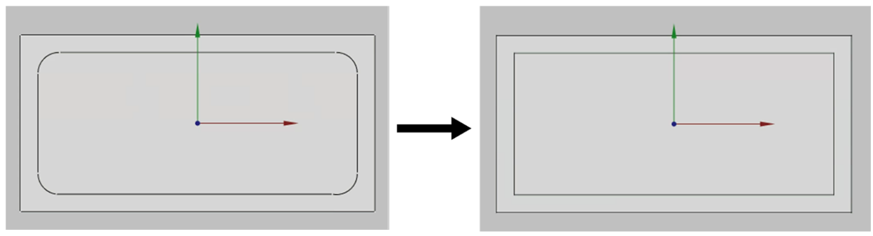
Removal of the coaxial connector is quite frequently done if the connector is placed on the edge of the substrate, where the connector can be removed completely.
If you are using a panel type connector, you can remove the connector and create a cutout where the connector was placed previously.
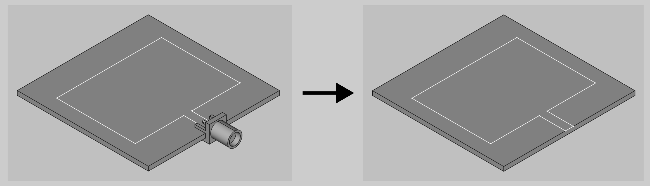
To create a cutout feed in FreeCAD:
- Create a sketch on the patch and draw a circle of where the port will be.

Extrude the port through the patch.
Choose the patch and cylinder objects and click Cut boolean to create a hole in the patch.


note
You should take into account that using the coaxial port can slightly increase the accuracy of the results but will increase the computation time.
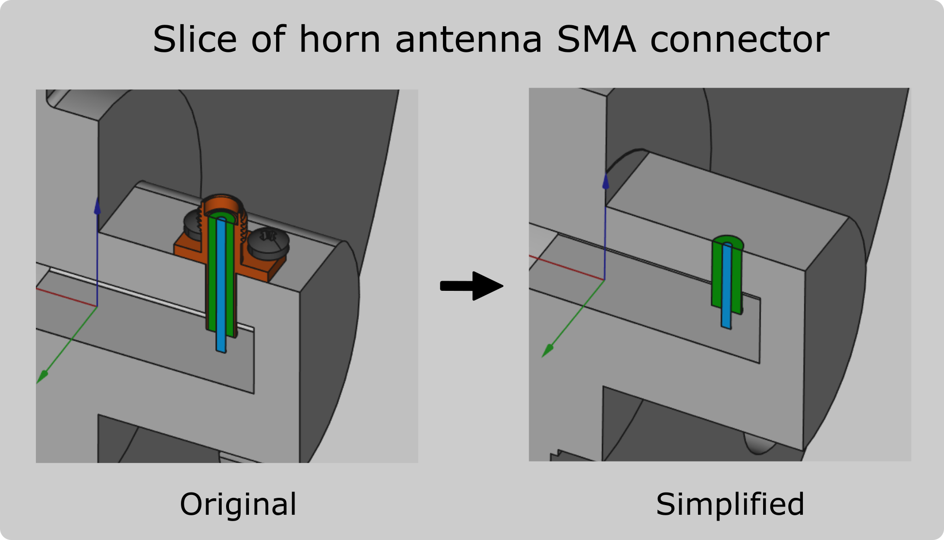
In cases where the coaxial connector functions as a probe, such as probe-fed horn antennas, you can simplify the connector to a simple cylinder assembly!
Limitations
Although the process of defining a port in CENOS RF is incredibly straightforward, there are a few things to keep in mind.
Discrete port terminal selection
Currently, the possible points of terminal selection are fixed. On a straight edge, you will be able to place a terminal on its leftmost and rightmost point and in the middle of these two points.

However, this shouldn't affect the accuracy of the results, as the solver finds the shortest path possible between the terminals along the mesh cells to excite the model.
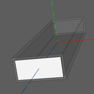
Waveguide port geometry
CENOS RF currently only supports rectangular faces for the Waveguide port. Try to avoid curvatures in the port as this will not allow you to move forward with the simulation.
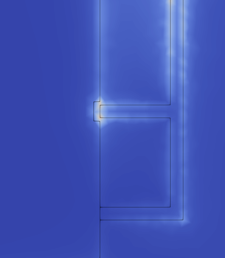
Mesh density around the port definition
On rare occasions, the mesh around the port definition might be too rough. If you notice a rough mesh (jagged Electric Field distribution) around where you defined the port, go back to the Mesh Generation screen, enable manual meshing and apply a finer refinement along the edges or face of the port.