Physics and simulation setup
Overview
Setting up the physical settings in CENOS is simple. On the left side you can see the preview window of your geometry.

On the right you can find the physical definitions of your model. You can switch between the definitions using the tabs. The material definitions are sorted by role, so you will see the volumes and surfaces with the same role under the same tab.

Definitions
In Physics the definitions are quite straightforward.
Simulation Control
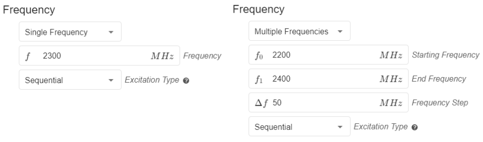
In Simulation Control you need to select the frequency of your model, choose whether you want to enable Sequential or Simultaneous excitation of the defined ports and enable the Parametric Study. You can set one frequency, or do a frequency sweep to test your model for a whole range of frequencies.
In the case that you are using multiple ports, you will also be able to select whether you want to use sequential or simultaneous excitation.
Computation Settings
You will also find Computation Settings, where you can select the algorithm to use:
- Fast.- It uses 2nd order mesh elements.
- Accurate.- It uses 3rd order mesh elements. This algorithm can provide more accurate results but will increase the computation time.
You will find the definition of the number of processes. The value determined here defines the number of processes that will be calculated in parallel. This will help you to significantly reduce your calculation time! Note that this will increase the resource usage of your PC, so try to choose a value that is appropriate for what your computer can handle.

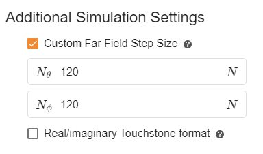
Additional Simulation Settings
Within this section you can customize the total step count for the far field generation. Increasing the values will help you to have more values in the far field results and therefore a higher resolution.
You can specify whether you want the results of the Touchstone file to be displayed in real and imaginary format instead of dB and angle.
The Touchstone file is saved in the folder called "extra_results" located in the general folder of your case (case_folder\extra_results). In this same folder you will find the Smith Chart that you can use as a tool for impedance visualization!
Parametric Study
With CENOS RF software it is possible to create a parameterized model and change the dimensions of your geometry in a simple way.
Without parametric values, each geometry modification requires the creation of a new model from scratch or going back to previous stages of the simulation to make the required changes, which can be very time consuming. If the model is parameterized, geometry modifications only require changing the required parameter in the Simulation Control.
How to use Parametric Study?
The Parametric Study feature is available through the Geometry Editor approach. The first step is to parametrize your geometry within FreeCAD.
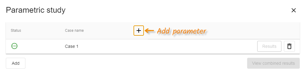
Once you have sent your geometry to CENOS and are in the Simulation Control, you will need to enable the parametric study and click on CONFIGURE.

The parameters you have previously defined will appear in a new window, you can add one or more parameters! You can also add as many cases as you need to simulate - just click Add and a new case will be created.
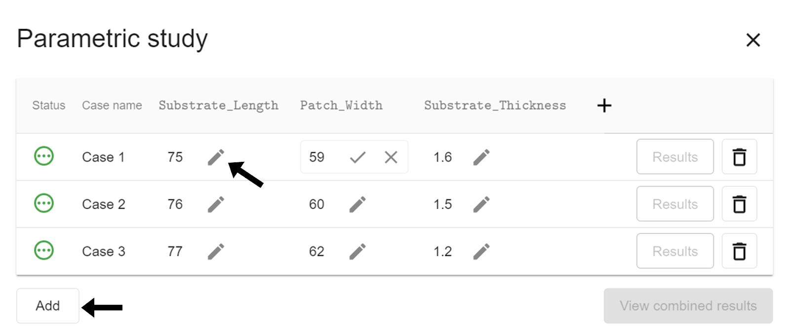
When you have finished making the necessary adjustments, you just need to close the parametric study window and continue with the usual workflow.
Limitations
Geometry overlapping
By changing the parameter values, geometry can become non-physical, i.e. elements can overlap each other or sketches can be left out of a solid surface. It is necessary to avoid these situations so that the simulations work properly and the results are obtained without any inconvenience. Make sure that your geometry has the necessary constraints and that the parameter dimensions are physically possible.


Volumes
For volume objects of your model you only need to define the material it is made of.
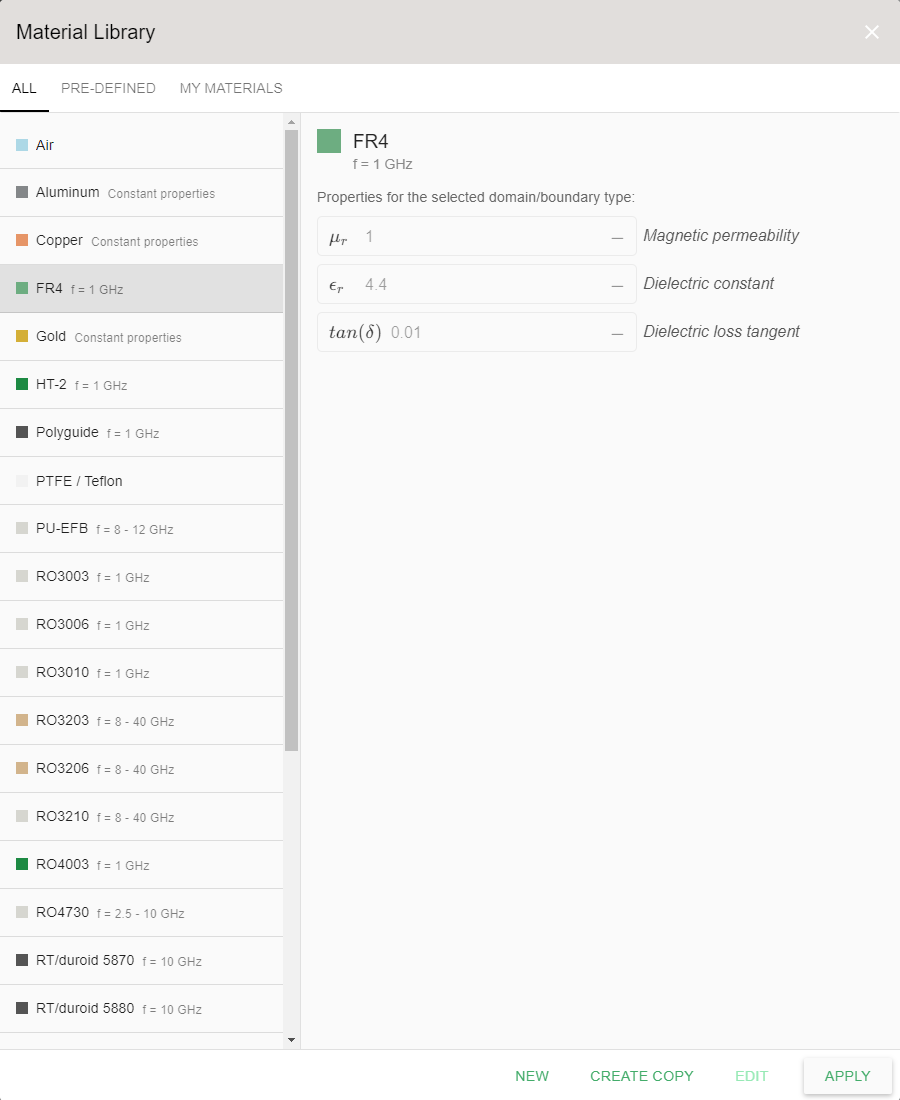
You can write the name of your material directly into search bar, choose from CENOS's built-in material library or define your own material!

You can browse through the whole material library by clicking on Select... and see all the defined materials. If you have defined some new materials, you can see them all in the MY MATERIALS tab.
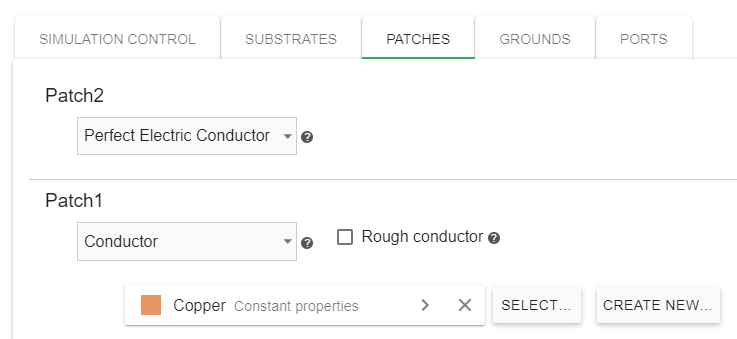
Surfaces
The surfaces of your model, which are typically conductive materials, are automatically assigned as perfect electric conductors, but you are able to redefine them as real materials as well, such as copper or aluminum.
Ports
After you have defined your ports in the Geometry section, you can define the configuration of your ports in the PORTS tab.
Lumped ports
When using a discrete port you can define several of its parameters, one of them is the complex part of the impedance, which can be configured as reactance or frequency-dependent capacitance.
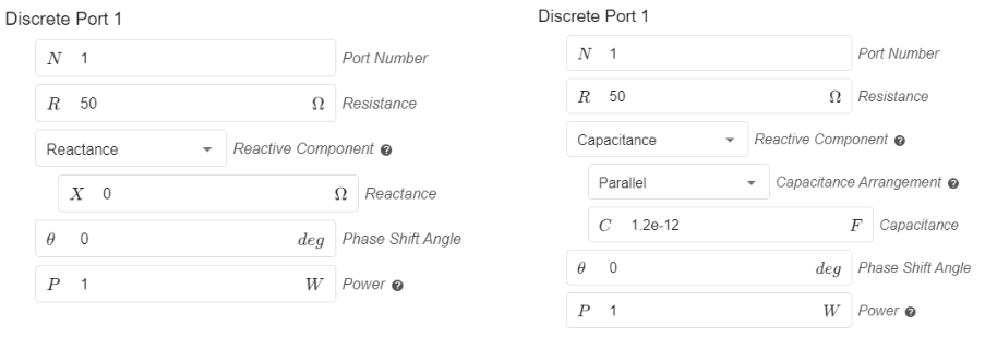
You can also define the phase shift angle, as well as the input power of each port when using sequential excitation.
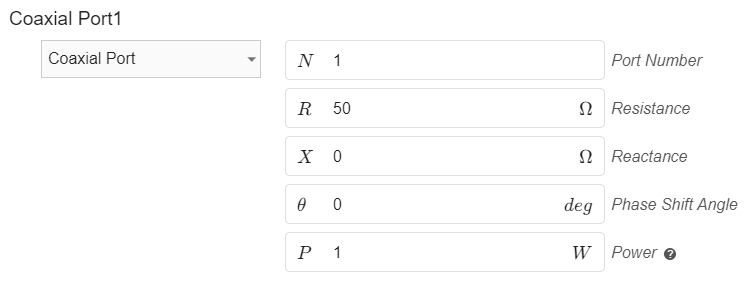
Coaxial port
The coaxial ports in CENOS are defined using one face of the dielectric. You can easily modify the input impedance, phase shift angle and input power.
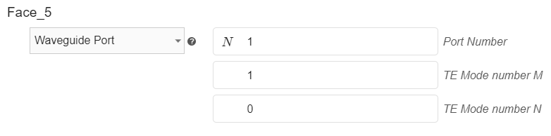
Waveguide port
In the waveguide ports you can change the port number and select the Mode you will use.
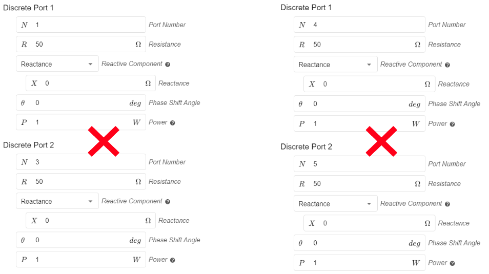
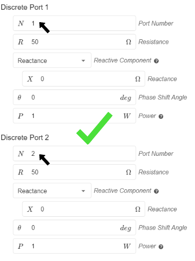
note
When using multiple ports don't forget to number each one with a different number sequentially, starting at number 1. If there are ports with the same port number this will cause problems!
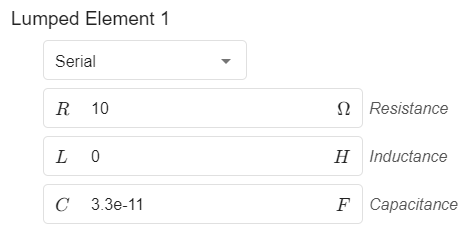
Lumped elements
If you have defined some lumped elements in your model, you can define the resistance, capacitance and/or inductance for each element in the Lumped Elements tab. Here you can also switch the configuration of each element between Serial and Parallel.